

Technical data
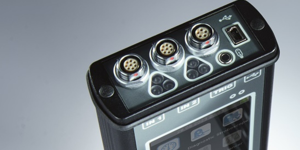
| Input Channels | 4 x AC/DC, 1 x TACHO for speed probe/external trigger |
| Frequency ranges [-3 dB] |
|
| Sampling mode | Fully simultaneous for 3 channels |
| FFT resolution | 25 to 25.600 lines |
| Display | Colors: 240 x 320 pixels |
| Built-in LED Stobeoscope, LED Torch | |
| IR Temperature Measurement | -70 °C to +380 °C (-94 ºF to +716 ºF) |
| Interface | USB 3.0, 2.0 compatible |
| Operating temperature range | -10 °C to + 50 °C (-14 ºF to +122 ºF) |
| Power | Battery 10 hours of continuous operation |
| Case | IP 65rating, aluminium heavy duty |
| Size & Weight | 230 x 82 x 32 mm, 780 g |
| Languages | German, English, French, Spanish, Portuguese, Italian, Russian, Hungarian, Romanian, Polish, Czech, Turkish, Chinese |
Included modules
Messmodus
This module includes the following basic vibration measurements
- Overall vibration
- Provides a traffic light display of vibration values based on pre-setup limits. The color indication is according to ISO 10816 standards.
- Overall (RMS) and Peak values are displaced with the following frequency ranges: Velocity (10 Hz – 1000 Hz) or Acceleration (0.5 kHz -25.6 kHz)
- FFT Spectrum
- In mm/s (RMS) with 3 maximum peaks (2 Hz – 200 Hz)
- Displacement values
- Uses the following frequency range of (2 Hz – 100 Hz)
- Time Signal
- Used for roller bearings (0.5 kHz -25.6 kHz)
- Vibration in RMS for gearboxes/bearings in the following frequency ranges (0.5 kHz -1.5 kHz), (1.5 kHz -5 kHz), & (5 kHz -25.6 kHz)
- Temperature
- Displayed in colored ranges using IR temperature sensor
Diagnostic
This module is an expert system for automatic detection of possible machine faults.
Displays the following faults:
- Overall machine condition
- Overall bearing condition
- Severity of unbalance fault
- Severity of mechanical looseness
- Severity of misalignment
- Displays via text if the found condition is good or severity of fault or provides a velocity spectrum displayed on the bottom of the screen.
Stroboscope
This module visually “freezes” the machine movement and checks its rotating parts.
Additional Modules that can be added
- Tracking
- Data Collection
- Analyzer
- Balancer
- Ultrasound
- Recorder
Further information on the optional modules of the SVA 90
Tracking
With the Tracking Module, resonances in the system can be determined by the measurement and graphical display of the amplitude and phase angle of the rotational vibrations as a function of the speed. The Tracking Module uses the raw vibration signal and visualizes the amplitude and phase angle in a bode, Nyquist, FFT waterfall diagram, and numerical reading.
This ensures dedicated balancing outside the range of machine resonances.
Data Collection
One of the fundamental principles of condition monitoring is data collection based on predefined alarm limits. The Data Collection module is used for the periodic collection of vibration data of the balance of plant machinery. Simply create a route tree with measurement points and locations in the Schenck Diagnostic Center Software and upload the route in the Smart VibroAnalyzer 90. With the uploaded route you are prompted by the unit to move from machine to machine with specific measurement points to efficiently collect data.
The Smart VibroAnalyzer will notify you of an alarm situation that can easily be reviewed on the unit to provide onsite feedback. After the route is completed, the collected data can be transferred back to the Schenck Diagnostic Center. Software via USB-C cable to store readings, review trends, analyze data, and provide reports.
Analyzer
Early Detection and diagnosis of machine faults are key principles for planning and executing plant maintenance.
With the Analysis Module, the user can select the type of measurement (from simple overall values to FFT’s and time signals, to more advanced measurements such as orbits using displacement / proximity probes) and set up multiple, synchronized, simultaneous measurements from all channels with settings such as frequency range, sampling rates and units.
The Smart VibroAnalyzer 90 feature frequency ranges of: 0.5 Hz to 25 kHz with (64 kHz sampling), respectfully, to identify most faults.
If more detailed vibration analysis is needed, the Recorder Module allows the user to record live data from a machine and perform post-processing of the data on the unit itself. The user can perform post-processing of the same raw timewave form multiple times allowing for a more precise analysis of a detected fault to determine the location and severity. In addition, the data can be transferred to a host computer with the Schenck Diagnostic Center Software for reporting.
- Real-time FFT
- Demod/envelope analysis
- ACMT – low speed bearing analysis
- Order Analysis
- Orbit Measurement
- User Band Pass Analysis
- Frequency Range: 0.5 Hz - 25 kHz (64 kHz sampling)
- FFT Resolution: Min: 100 lines, Max: 25,600 Lines
- Fully simultaneous for 3 channels
- Crest Readings
- Time signal measurements
- Phase Shift
- DC Measurements
- Centerline Measurements
- Smax
- Overall Measurements
Balancer
This module allows for balancing equipment in situ, both in the field and during final assembly, providing a quality product.
- Multiple balancing types such as Polar (0-360 degrees), component and fixed weights
- Flexible Visualization of balancing: polar plot and table overview
- Optimizing the final vibration level at the two bearings supports in an early stage while balancing in a single plane
- Allows for Rotor setting to calculate balance quality according to ISO 1940
Ultrasound-Recorder
This module uses a microphone (sold separately) to allow for the measurement of sound inaudible to the human ear.
- Typical applications that benefit from the use of ultrasound measurements are air leak detection, electrical arcing, or early bearing fault detection.
Recorder
This module is a unique measurement mode that allows you to „record” the raw signal from the sensor i.e. the raw signal from the machine.
- The Recorder allows you to then post-process the signal later on the unit.
- The user can perform the post-processing on the same raw data multiple times.